Pages

Showing posts with label Objective. Show all posts

Friday, 17 April 2015

The components for ten O2+ODAC combos have arrived

Earlier this week I went to pick up the package containing everything I need for the ten O2+ODAC headphone amplifier combos that I am going to build. It was heavier than I thought it would be but then I remember that the power adapters and the cases do have a bit of weight to them after all.

I have been incredibly busy this whole so I haven't had time to do anything else but open the package making sure everything was there, which it of course was.

Cases, panels and knobs in the bottom right. Power adapters in the bottom left. Component bags in the top. PCBs in the middle and USB-cables to the left and ODAC boards to the right.
Today I had a bit of spare time so I decided to start marking the resistors. Previously I have only been building the amplifiers one by one and so I have had to measure the resistors every single time which of course takes a lot of time. I estimate that it takes maybe 15 minutes to properly mark all the resistors in one bag of components. I have ten now. So I figured that if I mark one bag properly I can use it for reference when doing the other nine bags and so I should be able to save a lot of time. This way each bag took about four minutes so I guess I saved over one and a half hours of work.

Since there were no bits of paper on the two single resistors I had to make custom "flags" for them. A bit of tape and a small piece of paper worked just fine for labelling them. 

I am not sure when I will start building these because so far I haven't had time to do any advertising and I haven't gotten any requests yet either. This was thought to be a summer job but the earlier I can start advertising and selling the better it is. Selling ten of these in Sweden is likely going to take a while.

If you are interested in buying, send me a message at phimusicblog@gmail.com.

Monday, 23 March 2015

Will be ready to sell O2+ODAC combos in Sweden within a week or two

I have good news for my Swedish readers. I just placed an order on ten O2+ODAC kits and I'm hoping I will get them by the beginning of next week and I'm hoping to build at least one or two before going on holiday over easter. If you want to buy just an O2 and not the ODAC, let me know and I'll make special arrangements for that.

My plan is to sell a finished O2+ODAC for ~2000SEK+shipping. I will offer custom gain settings for no extra cost. Unfortunately I will not offer any other extras such as 6.3mm output, back panel power or other colors than black (which seems to be the most popular).

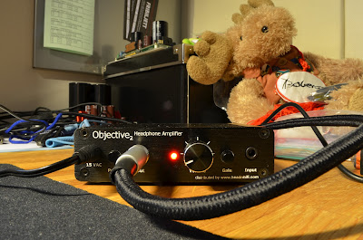
Finished black O2+ODAC
So, what do you get when ordering an O2+ODAC combo from me? You get a fully assembled, fully functional amplifier and DAC. You get a 90cm gold plated (looks fancy) USB-cable. Underneath the case there will be small rubber feet to prevent scratches and stop the case from sliding around on your desk. The volume knob will be black brushed aluminium for a nice quality feel. The power adapter is a very compact one with a cord that is long enough for most people. I estimate it is around 1.5m. On request I will add gain resistors which can be useful if you want to switch gain settings in the future. I will make it so that no soldering will be required to change gain resistors, just pluck them out of the socket with a tweezers and put in the new ones. Standard gain will be 2.5x/6.5x. I haven't actually had any headphones that have needed more than 1x but for an example the Sennheiser HD600 needs a high gain. My Denon AH-D2000 and my Koss Porta Pro are just fine with 1x. 

If you are interested in buying one from me, contact me at phimusicblog@gmail.com

If you are not in Sweden but you still think that this looks like a kickass amplifier combo, then check out this site and buy your own DIY-kit.

Thursday, 19 March 2015

Planning to start selling O2+ODAC headphone amplifier + dac combos again

Hello dear readers,

A while ago I had a service where I would build O2+ODAC combos for people for a small fee. I quit that partially because I felt I wasn't paid enough and because I didn't feel like I had the time. However I will be getting more free time now so I could start doing it again but then there is the problem of monetary reward for me. Previously I would end up with a really crappy hourly wage if I would just take single orders for people and build them on request. I am now planning to invest in buying maybe 8-10 sets to build and sell to people. For me this would mean that I make more money per unit sold and you as a potential customer wouldn't have to wait ~1-2 weeks, I could ship as soon as you have paid me and the combo would be in your hands in one or two days.

As I mentioned this will be an investement, a rather big one considering I'm on a student's budget. So before I spend a lot of money ordering the components I would like to know if there is any interest in buying pre-assembled ready-to-run O2+ODAC combos. Remember, this is only for people in Sweden. If you are interested, let me know! Send me an email at phimusicblog@gmail.com or post a comment below.

My plan is to order within a week or two if there is a big enough interest.

Also, I have recently become an affiliate of www.headnhifi.com so if you want to buy any of his products, be it a ready-made amplifier, ODAC or maybe even a DIY-kit, please feel free to use these links below if you want to support me since I get a small percentage of the money you spend on his website if you use the links below.

Full O2 amplifier DIY-kit
O2 amplifier DIY parts-kit
ODAC DIY board only
O2+ODAC headphone amplifier+dac combo
O2 headphone amplifier
ODAC RCA version

Remember, let me know if you are interested! Also, if you are interested in buying anything else from his site and you are intimidated by buying from overseas, let me know and I can add it to my coming order and you can buy it from me instead.

One last thing, if you are not in Sweden but you are still interested in building your own amplifier, use the links above and for instructions check my construction guide and my notes here http://phimusic.blogspot.se/search/label/Objective

If and when I start building again I will create a new, much more detailed step for step guide including everything a total beginner will need to know to build a complete O2+ODAC combo. I may even do a full video guide if there is enough interest.

Saturday, 20 July 2013

Objective2 headphone amplifier construction guide

Buy your own O2-kit here

Start with measuring all the resistors and labeling them.
Smallest parts first, so solder all the small resistors like this.
Add the diodes, make sure to solder them in the right direction!!! Solder the medium size resistors now too.
The IC-sockets have such short legs to it's a good idea to add them early.
Add the two big resistors at the bottom of the board. Keep 2-3mm distance between the resistors and the board since they can get warm during operation.
Add some of the small capacitors.
Add the slightly bigger capacitors on the bottom right of the board.
Add the blue capacitors.
Solder the LED first, it's important that you get it close to the board and pointing straight forward. Next att the 3.5mm sockets, they snap in to place so they are easy to solder.
Add the power socket. Solder one leg first, reheat the joint and push it in place and then solder the remaining legs.
Add the switches. This can be a bit tricky. Solder only one leg first. Reheat the joint and push the switch into place and make sure it is close to the board and pointing straight forward. If not you will get trouble with the front panel. Solder the rest of the joints when you feel satisfied with the positioning. Add the white square capacitors.
Add the volume potentiometer, try it in the case with front panel on to make sure you put it in the right position.
Volume control soldered to the board. For this kit I had to use the two row in the front.
Now add the two round brown capacitors.
As you can see in the picture there is a bridge between them. Solder the outer legs first, push them in place and then solder the bridge between them. You will need quite a bit of solder here. If you look closely you can see that the on/off switch has only been soldered as one place so far.
Add the four big capacitors. Solder one leg first, push them in place and solder the rest.
Solder the battery connectors. If you are going to mount an ODAC on the board you should only solder the two connectors to the left. If you're not planning on using an ODAC, solder both pairs. Make sure they stand straight! Solder one leg first, push to place and solder the rest.
With battery connectors on board. I will be mounting an ODAC to the board so I only soldered the left pair.
Add the ESD-sensitive parts. Be careful with these and try to avoid touching the legs. Solder smallest first and finish with the biggest. The two big ones to the left must be close to the board, otherwise they will hit the roof of the case.
Reheat ALL joints on the board. This is because when you cut the legs off components the joints may crack and provide bad connection. Reheat all joints and the solder will flow out nice and smooth. Measure all resistances and voltages according to NwAvGuy's guide on his blog. If everything measures as it should, try with a pair of scrappy headphones. Don't forget to add the opamps, and make sure you put them in the right places and in the right directions! This is very very important and triple check this before starting it up for the first time.
Don't use your expensive headphones the first time you are playing it. If something is wrong, you don't want to kill your $300 headphones. 

Sunday, 24 March 2013

Delayed step-by-step construction guide

Unfortunately the step-by-step construction guide for the O2 amplifier will be delayed  a bit. I have been very busy this weekend and I doubt I'll have enough time during the coming week. We'll see, I might divide it up into several smaller pieces maybe...

Wednesday, 20 March 2013

#3 finished

I have finished the combo and I'm actually listening to it right now. No guide and no pictures yet, I don't have the time to finish that tonight. I guess I'll do it on Friday evening or during the weekend. I'll send the amp to the customer on Friday but I'll make sure to take enough pictures before that.

Old picture of my amp (on the top) and #2 underneath.

Tuesday, 19 March 2013

Another O2+Odac combo coming, with step-by-step construction guide

Short post, should go to bed ASAP.

Picked up a package today containing an O2+Odac combo which I am building for a guy. I will take the opportunity to make a step-by-step construction guide to show you how simple it is to build. More about that tomorrow evening when I have started building.

Old picture of my O2+Odac combo

Wednesday, 28 November 2012

Building another O2+ODAC combo

The past few days I've been building another Objective amplifier+DAC combo for a guy at www.sweclockers.com

He ordered the stuff and got it sent to me, I picked it up on monday afternoon and started building directly. The first evening I finished most of the O2 board, except one of the battery terminals and the power connector.
On day two I sanded the legs of the power connector to make it fit through the holes and I used a glove to mount the last battery terminal (it gets very very hot!). For that job I borrowed a dremel copy from my neighbour. It was the first time ever I was using a dremel but it was simple and straight forward. Really liked it!

I then measured all the voltages and everything was fine, well under the limits. Tested it briefly with my phone as a source and a pair of old crappy headphones connected to it. Everything sounded as it should.

It was then time to mount the ODAC to the O2. Again using the dremel to cut the bolt from ~40mm to ~10-15mm. Very handy but it made a nasty noise. Found a broken CAT5-cable in a drawer and cut off ~10cm and took two of the pairs and stripped the insulation. Only strip a couple of millimeters here, not a centimeter as with speaker cables. Solder them to the board the right way this time, not as I did with my own amp.

Time to test run everything. Hook it up to the computer and test play it. No sound. No matter how hard I try there's no sound from it. I start double-checking all the wires and solder joints, nothing wrong. I try moving the ground cables to another spot on the board, no success. Then it hits me, maybe I didn't cut the traces on the O2 board well enough. The PCB was black so it was very hard to see. I look a sharp object and started scraping some more on the PCB and apparently they weren't entirely cut off. Cut them off properly and then it worked as it should.

Listened to it the whole evening and it sounded very very good, as it should. The product is now packed back into its box and I will ship it to the buyer tomorrow.

All in all it has taken me about 5-6 hours in total to build it. Much faster than the first time, because I knew where all the parts should be, I knew how to measure the voltages and I knew how to connect the ODAC to the O2. If you're a beginner and has very little or no knowledge of soldering and electronics, it might take 10-20 hours.

If you're interested in letting me build one for you, just send me an e-mail or write a comment or something.

And here's some pictures.

It's very nice to have a dedicated table for this!

All resistors marked and ready

Sanding the legs of the power connector with a dremel tool

My amplifier (the black) and the new silver one.

Up and running. The LED isn't yellow, it's red, it just looks yellow in the picture. 

Wednesday, 12 September 2012

O2 headphone amplifier + ODAC update #6 (against Asus Xonar Essence STX)

I haven't gotten to trying my O2+Odac against the Asus Xonar Essence STX until now. I've been so happy with the Objective product that I've been stuck with it :D

Today I lent it to one of my friends so he could try it with his AKG K271 MKII. So now I only have my Asus Xonar Essence STX and I must say the difference was bigger than I had thought it would be. The sounds isn't as dynamic as with the Objective, and the bass is a bit weaker and "muddier", probably because Xonar STX has a ~10ohm output impedance while Objective has ~0.5ohm.

The Xonar STX is cheaper than the O2+Odac, it supports 192kHz which the Odac doesnt (like that would make any noticable difference?). But still, Objective is the winner. It has superb audio quality for a relatively low cost. I don't think there's any way a commercial product at the same price of the Objective would stand any chance against it. I would even dare say that the Objective combo is the best you can get for <5000SEK (€590) or maybe even more.

Thursday, 23 August 2012

O2 headphone amplifier + ODAC update #5 (cables switched and gain resistors removed)

As the title says, I have switched the cables between the ODAC and O2 and removed the gain resistors R17 and R21.

Switching the cables may sound very easy, and I had expected it to take no more than a couple of minutes to do. I was wrong. Very wrong... It took me about 40 minutes in total because removing the wires was hard and then getting them back on was even harder. The holes had been messed up so I had to surface mount the cables on the back of the ODAC with a lot of solder to keep them in place...

Removing the gain resistors was easier though. It was pretty narrow but I could fit a tweezer between the resistor and the board. Then I heated up the joints on the back while pulling with the tweezer and eventually the joints let go of the resistor and it flew away through my room :P Now the gain is on a better level, no noise at all, even with the volume knob turned all the way up and there should be less distortion, especially in the higher frequencies.

Now when I have proper stereo sound everything sounds incredibly good and even if this amplifier costed 4000SEK (that's about $600/€480) it's still a very good buy.

I'm planning to sell this one though. Make some profit to buy myself a proper DMM and some soldering equipment. Remember I have only borrowed the soldering stuff from a friend, for a couple of months now. Should buy him some gift too for the profit I make. Then I'll build two-three more and keep one for myself and sell the rest. I'll be selling an Asus Xonar STX soundcard soon too, because as far as I can hear the O2+ODAC beats the STX.

Do I sound happy and satisfied? Yes, of course I am!

Wednesday, 22 August 2012

O2 headphone amplifier + ODAC update #4 (mono signal)

So, now I have found out why it sounds so much different and "boring" with the O2. It's because it's mono!
I've had my suspicions when soldering the cables between ODAC and O2 but I thought I'd better follow the guide... It turns out that in the guide the author had reversed the white and black cables which means that I have done it totally wrong and will have to open it up and reverse my cables. I have of course told Stefan Walter and Headnhifi about this and hopefully he will correct it.

I will fix this tomorrow and take some pictures of the process. Hopefully I'll end up with a kickass DAC+amplifier when I'm done :)

O2 headphone amplifier + ODAC update #3 (Up and running!)

Click for a bigger picture.

Click for a bigger picture.
So, today I finished this project. To find some M3 nuts and bolts I first went to a local store selling such things. They did have M3 bolts but they were 25mm long and I needed 10mm. Also they had no nuts but they told me I could go to a car workshop not too far away. There they provided me with three M3 nuts, bolts and washers (only needed one bolt, one washer and two nuts though). These bolts were also too long, about 35mm or so I think. Dry-mounted the ODAC on the board as it was suppposed to be. Took a red marker pen and marked the bolt and then cut it to the right length.

I knew I had some CAT5 wire somewhere, I had tried it for speaker cables a year ago or so. Started searching and found them pretty quickly. They're perfectly suitable for this application. I cut them into proper length and when I was searching for the cables I also found another cable suitable for the ground wire, more about that later.

So here's a picture of the ODAC mounted to the board with all wires soldered.

ODAC mounted to the O2 board. All wires soldered and tucked in between the boards. Do NOT use a thick stiff cable for this. Click for a bigger picture.

 I did the switched version, more about that can be found in this PDF. It was pretty simple and straight forward, a very good guide I must say.

How the board is put into the case. Click for a bigger picture.
I have read on the internet that it's a good idea to scrape some paint off the inside of the case somewhere and then put a cable from the front center pin of the 3.5mm input to the case. This for some kind of ground making the amp slightly quieter. This was easily done by using the wire I found, a 1.5sqcm cable I think. Soldered one end to the pin. I then peeled off the insulation of the other end, realising that I had to take away some of the strands to be able to do as I had planned. I cut off maybe 2/3 of the strands, then spread them out a little like a fan. I scraped some paint off just by using a flat screwdriver. The paint goes off easily. Then put the strands at the surface where the paint is scraped off, then put the back plate on, hold it tight while screwing it to place clamping the strands between the back of the case and then back panel.
This is how the scraped surface looks like.
I seem to be unable to rotate this picture, so I'll leave it like this... Well here you can see the green ground wire running under the board to the back of the case where it's clamped between the backplate and the case.

Tuesday, 21 August 2012

O2 headphone amplifier + ODAC update #2

I borrowed a better DMM today (Thanks to Pelle Nilsson) and measured the voltages with that and everything was fine and as it should be. Mounted the remaining chips in their sockets and right now the board is mounted in the case (sorry, no picture yet). Tomorrow I will try to figure out a good way to connect the ground wire to the chassis and then try the amp for the first time. I wont be using my Denon headphones though, because if there's something wrong I don't want to damage my expensive gear. Instead I will use a pair of old Steelseries Siberia V1 headphones, I don't care if they blow up since they'll never be used again anyways. Hopefully everything will be all right.

I will also continue my search of two M3 bolts and nuts so I can mount the ODAC to the board. And before finishing it all I will need to put some kind of spacer between the board and either the back or the front of case. There is maybe 1mm clearance so the board is going back and forth which is a bit annoying.

Monday, 20 August 2012

O2 headphone amplifier + ODAC update #1

I have now mounted C6 and C7 to the board. After that I read the initial testing guide over at http://nwavguy.blogspot.se/2011/08/o2-details.html#initialdiytesting

Checked the power supply voltages with success (I think). According to the article the DMM should read 23-24V while mine showed 25V. Nothing got warm or hot as far as I could feel. Turned the power off and installed U2 and repeated the test above with the same results as should be. Then I moved on to the second test and this is where I hit some problems. I measured from the negative battery terminal of BT1 to pin #4 of the empty U4 socket and it should be close to -11.8V but my DMM showed -0.00V. Switching the probes gave me 25V reading. I then measured from the same negative BT1 to pin #8 of the same socket and this should give 11.8V but I got 25V again.

So right now I'm waiting for help, hoping that somebody will answer me in the O2 thread at diyaudio.com

O2 headphone amplifier + ODAC

So, I've bought an O2 headphone amplifier diy kit from www.headnhifi.com and also a pre-assembled ODAC board (don't want to DIY that one!). Everything was packaged very well, credits to Stefan at headnhifi for that.
After opening the box...  Click for a bigger picture.

All stuff that was in the package.  Click for a bigger picture.


I started with measuring all the resistors and organizing them in a good way as to not mix them up. The bottom row of resistors are the extra gain resistors supplied with this kit.
Resistors measured and organized.  Click for a bigger picture.

Then I started by mounting the resistors on the board, starting with the smallest ones and ending with the biggest ones. I've heard it's a good idea to not mount the big ones in the bottom right corner directly on to the board. It's good to keep a couple of millimeters between them and the board, probably because they will become hot during operation, I guess. I simply put a little spacer between the resistor and the board when I was soldering and then removed it when I was done.
Resistors mounted on the board.  Click for a bigger picture.
After the resistors came the small capacitors. I was a bit confused by C6 and C7 (just me being a bit dumb) so therefore they aren't mounted in this picture or the coming pictures. But they are supposed to be there and I will mount them them before finishing. I also mounted the diodes, remember to mount them in the right direction! It might be a bit easier to mount the diodes before the big ass resistors at the edge of the board. Remember "lowest components first on the board".
Diodes and small capacitors mounted, except C6 and C7.  Click for a bigger picture.
After that it was time to mount the DIP-sockets and film capacitors. Said and done...
Film capacitors and DIP-sockets mounted.  Click for a bigger picture.
After that it was time for the... I honestly have no idea what they are called but they are three-legged things and you'll see them in the picture (although slightly out of focus). Think they might be called rectifiers or transistors, not sure.
Three-legged thingys mounted on the board. One very small, two bigger ones and one really big one.  Click for a bigger picture.
Then it was time to mount some more capacitors. Started with the smaller round ones and the two tower-shaped ones. When mounting capacitors to the board like this it's very difficult to make them sit nicely to the board so I only solder one leg. Then I reheat that joint and push the capacitor flat to the board and adjust it so it's not leaning in any direction or so. This is also a good opportunity to double check that the polarity is right. Do NOT mount these the wrong way, then shit will happen :P Then I solder the second leg.
Some more capacitors mounted. Click for a bigger picture.
Time to mount the four biggest capacitors. Said and done using the technique described above.
Big capacitors mounted. Click for a bigger picture.
Now when everything (except the C6 and C7) are mounted it's time to put on the connections, switches and all that. The holes for the volume pot confused me a bit so I had to try mounting it in the case and putting on the volume knob. I found that the back set of holes worked best. Remember to get these items as straight as possible, otherwise it can be difficult to fit the front panel or the volume knob. I manage to get the LED and the volume pot pointing to the side a bit so I had to heat up all the solder joints and try to bend them straight. It worked but you should do it right from the beginning! Also, for the battery connections (only two are needed since I'll put the ODAC there) it's a good idea to use the same technique as with the capacitors, to get them as straight and flush as possible.
Connectors, volume pot and switches mounted. Click for a bigger picture.
Now when everything is kind of done I thought it would be a good idea to clean the board, I've heard that's very important to get rid of flux residues. I've been told that denatured alcohol is ok to use, we have something in Sweden called t-sprit which I've used before to clean off old thermal paste from CPU-coolers and such. I thought I had some of that at home but apparently I didn't. I found some k-sprit which is used for cleaning carburetors but it is denatured alcohol too so I soaked a bit of paper in that and wiped the board "clean". It didn't end up much cleaner than before so I think it didn't help much really, see the picture below.
The not so very clean board after using k-sprit. Click for a bigger picture.
To finish this I need several things. First I need something to clean the board with. Then after that I need two m3 bolts and nuts and some cables to mount the ODAC to the board. Then I need to mount the chips in the sockets (I thought it best to leave those in the ESD-bag for the moment).

I have also cut the ground traces as described on NwAvGuy's blog for mounting the ODAC to the board. I just took a sharp kitchen knife and careful cut the traces. Measured before with a multimeter and had close to 0 ohms and after cutting the traces it was not the same result so apparently I've succeeded in cutting them.