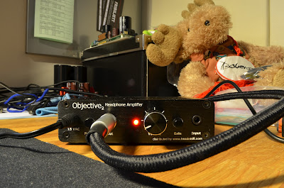
 |
| Click for a bigger picture. |
 |
| Click for a bigger picture. |
So, today I finished this project. To find some M3 nuts and bolts I first went to a local store selling such things. They did have M3 bolts but they were 25mm long and I needed 10mm. Also they had no nuts but they told me I could go to a car workshop not too far away. There they provided me with three M3 nuts, bolts and washers (only needed one bolt, one washer and two nuts though). These bolts were also too long, about 35mm or so I think. Dry-mounted the ODAC on the board as it was suppposed to be. Took a red marker pen and marked the bolt and then cut it to the right length.
I knew I had some CAT5 wire somewhere, I had tried it for speaker cables a year ago or so. Started searching and found them pretty quickly. They're perfectly suitable for this application. I cut them into proper length and when I was searching for the cables I also found another cable suitable for the ground wire, more about that later.
So here's a picture of the ODAC mounted to the board with all wires soldered.
 |
| ODAC mounted to the O2 board. All wires soldered and tucked in between the boards. Do NOT use a thick stiff cable for this. Click for a bigger picture. |
I did the switched version, more about that can be found in
this PDF. It was pretty simple and straight forward, a very good guide I must say.
 |
| How the board is put into the case. Click for a bigger picture. |
I have read on the internet that it's a good idea to scrape some paint off the inside of the case somewhere and then put a cable from the front center pin of the 3.5mm input to the case. This for some kind of ground making the amp slightly quieter. This was easily done by using the wire I found, a 1.5sqcm cable I think. Soldered one end to the pin. I then peeled off the insulation of the other end, realising that I had to take away some of the strands to be able to do as I had planned. I cut off maybe 2/3 of the strands, then spread them out a little like a fan. I scraped some paint off just by using a flat screwdriver. The paint goes off easily. Then put the strands at the surface where the paint is scraped off, then put the back plate on, hold it tight while screwing it to place clamping the strands between the back of the case and then back panel.
 |
| This is how the scraped surface looks like. |
 |
| I seem to be unable to rotate this picture, so I'll leave it like this... Well here you can see the green ground wire running under the board to the back of the case where it's clamped between the backplate and the case. |


looks schmick!
ReplyDeleteVery nice
ReplyDelete